Set in Stone
February 10, 2008
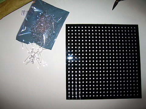
A bag of concrete, a few hundred feet of fiber-optic cable and LEDS, an Arduino and some LED Drivers can make a cool interactive concrete interface. We call it “Set in Stone“.

PLANNING
We broke down our project to the various components:
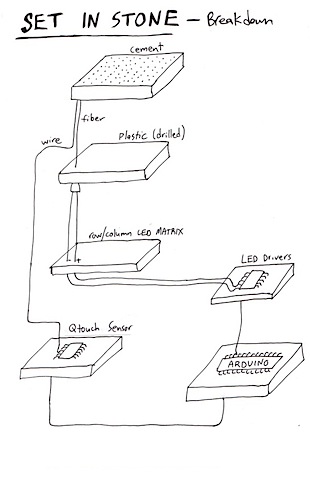
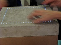
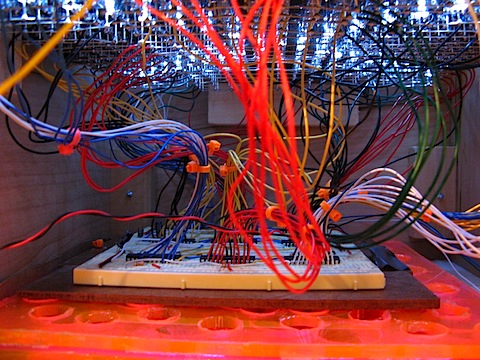
Each concrete block will be 13“ x 13“ x 2“ cast with 400 optical fiber-optic cables, creating a 20×20 LED grid. Each fiber-optic cable will goes to a plexi-glass panel that has holes for LEDS on one side and fiber-optics on the other. That way each LED is associated with one fiber-optic which will allow us to control exactly what is displayed on the cement surface.
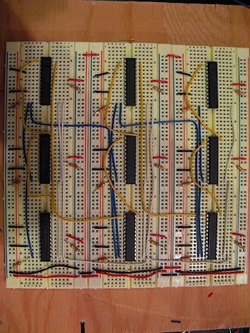
The LEDS will be connected to 9 LED Drivers (MAX 7219) that connect to an Arduino. This allows to program each LED individually using the Matrix Library. (really simple code)
To make the cement touch sensitive we ran solid-core hookup wire from the cement to a Qprox sensor that is also wired to the Arduino. When you touch the surface it will change the patterns on the cement. Originally we wanted a multitouch surface. One that you can draw with using you fingers. For that we cast each fiber optic cable paired with a wire. However, in the end we were unable to implement multitouch capability and so the projec moved from multitouch to single touch and we trimmed the extra wires.
LED MATRICES
We purchased four 11“ x 11“ plexi-glass pieces from Canal Plastics. We designed an Illustrator file with a grid of 400 holes for the LED’s and the 400 fiber-optic cables. We had them laser cut at the AMS Center at NYU.
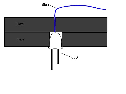
So each LED addresses one fiber optic cable we lay one plexi on top of the other like this:
Wiring the LED’s is simple but it’s also a lot of work. Alternatively we could have gotten pre-made LED Matrixes. They come in different sizes and colors and it would have been faster and easier. But we were going DIY all the way. To solder the Matrices, in each row all the Positives are soldered together and all the Grounds are soldered together.


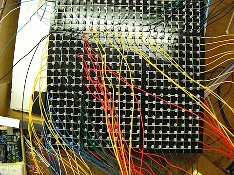
Each MAX-7219 LED Driver controls an 8×8 LED Matrix. We needed nine:
After wiring we connected the LED Matrixes to the drivers:

MAKING A GRID
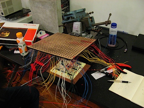
One question we had was how to get the fiber-optics cast in the cement so that they form a perfect grid. We got a piece of 13“ x 13“ foam core the same size as the cement, laid out a grid on the foam, using the plexi-glass. Then we poked holes in the foam and stuffed it with the fiber-optic and wire pairs, holding it up in bunches, trying to keep it neat:


POURING CONCRETE
Pouring our concrete was a multistep process. First we built a wooden form using 1×8 lumber and 1/2inch OSD Plywood. Since the final dimensions of the concrete was to be 13”x13” we made sure the inside dimensions of the forms was 13×13. We screwed the 1×8 pieces together to form the sides of the form and then we screwed them down to the plywood. In order to make sure they were water tight, we put a bead of caulk down between the 1×8’s and the plywood. Also we ran caulk up the corners of the inside of the form to make them smooth.
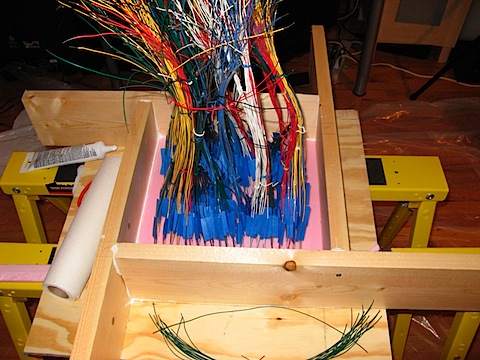

After we placed the foam pieces with our wire/fiber grids carefully within the forms we then caulked around the edges of those to ensure that none of the concrete leaked down intot he form and so that we would have smooth edges. After letting the caulk dry we sprayed the whole form with Pam cooking spary so that the concrete wouldn’t stick.
We chose to use Buddy Rhodes Concrete counter top mix because of the small aggregate.

Because our wires and fiber were so close together we didn’t want large pieces of stone moving them off of the grid. Also the concrete mix dries to bone white instead of grey allowing us to color it in whatever color we wanted.
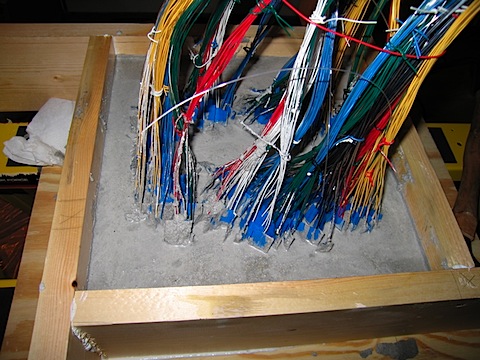
We mixed the concrete to about oatmeal consistency in a plastic bucket and spooned it with a large spoon into the mold. We were very careful to avoid moving the wires and the fibers. Once we had a good amount of concrete in the form we vibrated the form by hitting it with a rubber mallet from below for about 15 minutes ( scares your neighbhors pretty good) to get the air bubbles out. After that you let it cure for about 24 hours covered with plastic. At the end of that time we removed the plastic and loosened the form allowing the sides to dry for another 24 hours. Then we pulled it out of the form. At this point you should have a solid concrete block attached to a foam block.


AFTER DRYING
The fun part is getting the foam off the concrete. It involves a lot of pulling and a bit of a mess. The basic idea is to get as much foam off in as large chunks as possible. We found that breaking the edge foam and then moving to the center of the foam made it easier. Be very careful of the wires as they are sharp and you dont’ want to break them while doing this.


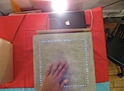
After the foam was off we proceeded to plug each of the fiber optics into the laser cut plexiglass that was made for them. A good flashlight really helps at this point so that you can line up the grid. We would shine a light down from the front of the the concrete into one fiber at a time allowing us to see where in the grid it went. As we had bunched the fibers into groups before the process was greatly speeded up. If we had had to find individual fibers from a huge bundle we would have driven ourselves crazy. Each fiber was also secured with a dab of Elmer’s glue to make sure it stayed in place. The fiber ends that poked through were trimmed flush to the surface of the plexiglass, so that they would be able to mate to the LED plate.

So now we have a 30lb concrete block tied very delicately to the plexiglass by fiber optic cable.


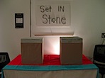
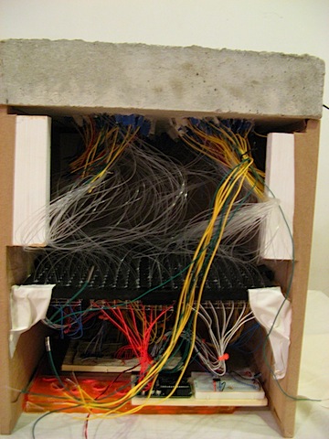
At this point we made a basic stand for the block out of MDF. Then we covered the MDF with kraft paper. After that we shoved everything carefully into the cabinets as shown.

FINAL PRODUCT
In the end you wind up with two interactive pieces of concrete that will interact with each other when touched. Some of our aims didn’t come true such as the multitouch, but we plan on implementing that in future iterations.